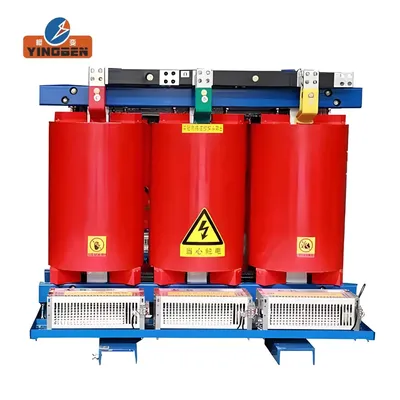
630 kVA 11 kV Dry Type Transformer
Cast resin distribution transformer for industrial facilities, commercial buildings and indoor substations. Primary voltage options include 11 kV, 22 kV and 33 kV, based on the approved project specification.
630 kVA Dry Type Transformer Technical Data
The following data describes the standard export offering and available project configurations. Final electrical and mechanical parameters are confirmed against the approved project specification.
| Rated capacity | 630 kVA |
|---|---|
| Transformer type | Cast resin dry-type distribution transformer |
| Standard primary voltage | 11 kV Standard offering |
| Additional primary voltage | 22 kV or 33 kV, subject to project review |
| Tested configuration | SCB14-630/10-NX2, 630 kVA / 10 kV Test evidence |
| Secondary voltage | According to project requirements |
| Rated frequency | 50 Hz |
| Phase | Three-phase |
| Vector group | Dyn11 or project-specific |
| Cooling method | AN natural air cooling; forced-air cooling available where required |
| Tapping range | According to the approved technical specification |
| Short-circuit impedance | Confirmed according to voltage class and project requirements |
| Enclosure options | IP00, IP20, IP23 or project-specific |
| Temperature monitoring | Winding sensors, temperature controller and alarm contacts available |
| Installation | Indoor installation |
| Connection arrangement | Cable or busbar connection according to the approved drawing |
| Applicable standard | IEC 60076 or project-specified requirements, subject to technical confirmation |
How should a 630 kVA dry type transformer be specified?
Capacity alone is not enough to define the transformer. The primary and secondary voltage, impedance, vector group, tapping range, enclosure, installation environment and applicable standard must be matched to the project’s single-line diagram and protection design.
Configuration for Projects in Vietnam and Malaysia
Voltage, ambient conditions and installation details are confirmed against the approved project specification.
11 / 22 / 33 kV
Primary voltage selected for the local distribution system
40°C / 45°C Ambient
40°C standard; 45°C tropical configuration available
Tropical Humidity
Configuration reviewed for hot and humid project conditions
Enclosure Options
IP00, IP20 or IP23 according to the installation environment
Cooling & Ventilation
Natural or forced-air cooling based on room conditions
Project-Specific Design
Final parameters confirmed before manufacturing
Technical note: 45°C ambient operation is subject to thermal design review, installation conditions, cooling arrangement and the required continuous rated capacity.
Type Test Report Available 630 kVA
Independent type test evidence is available for the SCB14-630/10-NX2 cast resin dry-type transformer. The report provides verified technical evidence for the tested 630 kVA / 10 kV configuration.
Selected Report Pages
Click an image to view the full-size page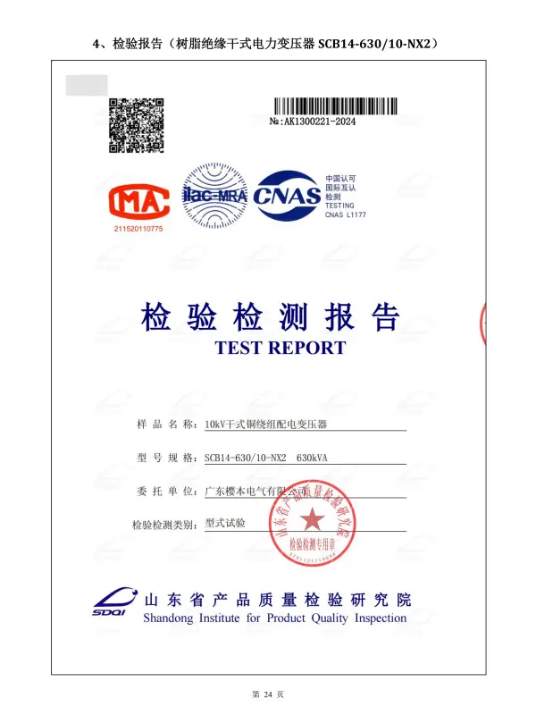
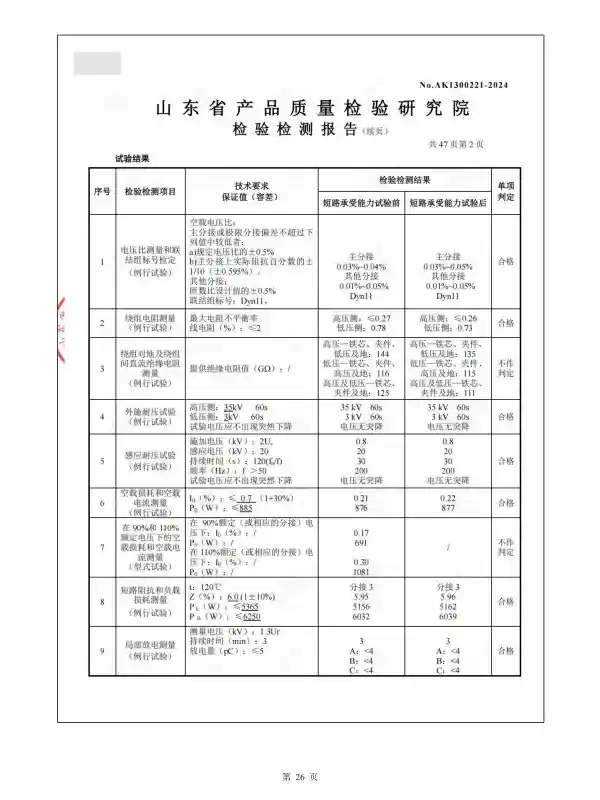
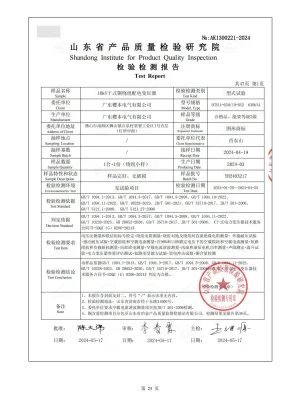
Report scope and project voltage
The available type test report applies to the tested 630 kVA / 10 kV configuration. For 11 kV, 22 kV or 33 kV projects, the insulation level, voltage ratio, tapping range, technical parameters and required documentation are confirmed separately during the project review.
Configure the 630 kVA Transformer for Your Project
A transformer should be selected from the electrical system and installation requirements, not from capacity alone. Before production, YINGBEN reviews the voltage ratio, load characteristics, impedance, enclosure, connection method and required documentation.
Voltage Configuration
11 kV is the standard export offering. Designs for 22 kV and 33 kV systems are available after project review.
Vector Group & Impedance
Dyn11 or another required vector group and short-circuit impedance are confirmed against the system design.
Tapping Arrangement
The tapping range and positions are selected according to the approved voltage regulation requirements.
Protective Enclosure
IP00, IP20 or IP23 options are available according to ventilation, access control and installation conditions.
Temperature Monitoring
Winding sensors, temperature controller, alarm contacts and cooling-fan control can be included where required.
Cable & Busbar Connection
Terminal position and cable or busbar interfaces are designed according to the approved substation layout.
Routine Testing Before Shipment
Each completed transformer is inspected and tested against the approved technical specification before shipment. Agreed routine test records can be included with the order documentation.
Test scope and document format are confirmed before production, especially where the project requires specific IEC clauses, witness testing or tender documentation.
From Project Specification to Delivery
Submit Requirements
Send the voltage, capacity, quantity, standard and installation conditions.
Confirm Technical Data
Review the data sheet, drawings, accessories and required documents.
Manufacture & Test
Manufacture according to the approved specification and perform routine tests.
Documents & Shipment
Prepare agreed test records, technical documents and export packaging.
Have a 630 kVA transformer specification?
Send us the single-line diagram, tender specification or existing transformer nameplate for technical review.
Compare Related Distribution Transformer Solutions
Select a dry-type, oil-immersed or integrated substation solution according to the installation environment, project layout and required equipment scope.
Dry Type Transformer Range
Review other capacities, primary voltage options, enclosure configurations and indoor distribution applications.
View Dry Type TransformersOil-Immersed Transformer
An alternative for outdoor distribution, utility applications and projects where an oil-filled design is preferred.
View Oil-Immersed TransformersCompact Substation
Integrates the transformer, medium-voltage switchgear, low-voltage equipment and enclosure into one project solution.
Explore Compact Substations630 kVA Dry Type Transformer FAQ
Technical and commercial answers for EPC contractors, distributors and industrial project buyers.
What is a 630 kVA dry type transformer commonly used for?
A 630 kVA dry type transformer is commonly used for indoor power distribution in industrial facilities, commercial buildings, infrastructure projects and indoor substations. Final capacity selection should consider the connected load, demand factor, motor starting current, harmonics and future expansion.
Can the transformer be supplied with an 11 kV primary voltage?
Yes. The standard export offering uses an 11 kV primary voltage. The secondary voltage, vector group, tapping range, impedance and insulation level are confirmed according to the approved project specification.
Are 22 kV and 33 kV configurations available?
Yes. A 630 kVA dry type transformer can be engineered for 22 kV or 33 kV systems. The applicable standard, insulation level, ambient conditions and test documentation must be reviewed before the final proposal is issued.
Is an 11 kV type test report available for this page?
The currently available type test report covers the SCB14-630/10-NX2, 630 kVA / 10 kV tested configuration. It provides test evidence for the 630 kVA product platform but should not be described as an 11 kV certificate. Documentation for an 11 kV project is confirmed during technical review.
Can it be configured for Vietnam and Malaysia?
The transformer can be configured for 11 kV, 22 kV or 33 kV distribution systems and for tropical installation conditions. A 40°C standard ambient design or a 45°C project configuration can be reviewed according to the site temperature, ventilation, enclosure and required continuous capacity.
Which enclosure protection levels are available?
Common options include IP00, IP20 and IP23. The correct enclosure depends on the electrical room, ventilation, dust exposure, access control and cable or busbar arrangement. The enclosure should be confirmed together with the approved layout.
What information is required for an accurate quotation?
Please provide the rated capacity, primary and secondary voltage, frequency, vector group, impedance, tapping range, enclosure level, applicable standard, quantity and delivery destination. A tender specification, single-line diagram or existing transformer nameplate will improve quotation accuracy.
630 kVA Transformer at a Glance
Request a Technical Proposal for Your 630 kVA Project
Send us your tender specification, single-line diagram or existing transformer nameplate. We will review the electrical parameters, installation conditions, accessories and document requirements before preparing the proposal.
- Primary and secondary voltage
- Vector group and impedance
- Enclosure and installation conditions
- Quantity and delivery destination
Advantages of Yingbeg 630 kVA Cast Resin Dry Type Transformer
- Safety First: Explosion-proof, non-polluting, and free of toxic gases, ensuring safety in dense urban areas like Bangkok or Jakarta.
- Tropical Resilience: Superior moisture resistance allows safe operation in 100% humidity environments without dehumidification, perfect for monsoon seasons.
- Robust Performance: Strong short-circuit resistance and high overload capacity (up to 150% rated load) handle fluctuating industrial demands effectively.
- Cost-Efficient: Compact design reduces installation footprint and costs while meeting or exceeding IEC standards for energy savings.
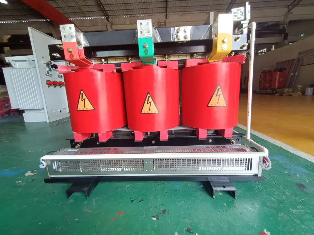
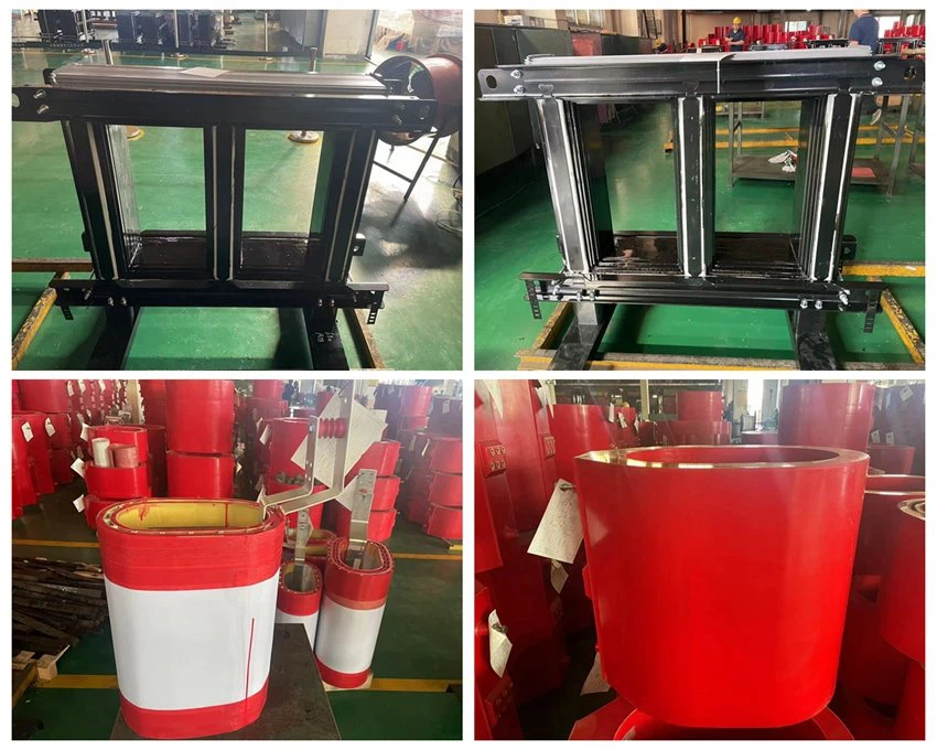
Yingbeg Transformer Core & Winding Technology
High-Efficiency Core: Built with precision-cut CRGO silicon steel using a 45-degree stepped full tilt stacking method. Each layer is insulated to minimize air gaps, reduce no-load current and noise, while extending the core’s lifespan.
Robust Windings: The low-voltage side uses high-quality foil or copper conductors designed for superior heat dissipation and short-circuit resistance. The high-voltage side features premium copper wires with an optimized structure to withstand lightning impulses effectively.
Technical Specifications: 630 kVA Dry Type Transformer
| Parameter | Specification |
|---|---|
| Model | SCB10-630kVA-6.6/0.55kV |
| Type | Resin cast dry type transformer |
| Rated Power | 630 kVA |
| Primary Voltage | 6.6 kV |
| Secondary Voltage | 0.55 kV |
| Frequency | 50 Hz |
| Phase | Three Phase |
| Cooling Type | AN/AF |
| Vector Group | Dyn11 |
| Winding Material | Aluminum |
| Standard | IEC60076 |
| Impedance | 4~6% |
| Tap Changer | NLTC |
| Tapping Range | ±2*2.5% |
| No Load Loss | 1.07 kW |
| On Load Loss | 5.88 kW |
| Accessories | Temperature controller, Cooling fans |
| Delivery Destination | South Africa (Delivered in 2023) |
| Remarks | N/A |
630 kVA Dry Type Transformer Technical Data
The following data describes the standard export offering and available project configurations. Final electrical and mechanical parameters are confirmed against the approved project specification.
| Rated capacity | 630 kVA |
|---|---|
| Transformer type | Cast resin dry-type distribution transformer |
| Standard primary voltage | 11 kV Standard offering |
| Additional primary voltage | 22 kV or 33 kV, subject to project review |
| Tested configuration | SCB14-630/10-NX2, 630 kVA / 10 kV Test evidence |
| Secondary voltage | According to project requirements |
| Rated frequency | 50 Hz |
| Phase | Three-phase |
| Vector group | Dyn11 or project-specific |
| Cooling method | AN natural air cooling; forced-air cooling available where required |
| Tapping range | According to the approved technical specification |
| Short-circuit impedance | Confirmed according to voltage class and project requirements |
| Enclosure options | IP00, IP20, IP23 or project-specific |
| Temperature monitoring | Winding sensors, temperature controller and alarm contacts available |
| Installation | Indoor installation |
| Connection arrangement | Cable or busbar connection according to the approved drawing |
| Applicable standard | IEC 60076 or project-specified requirements, subject to technical confirmation |
How should a 630 kVA dry type transformer be specified?
Capacity alone is not enough to define the transformer. The primary and secondary voltage, impedance, vector group, tapping range, enclosure, installation environment and applicable standard must be matched to the project’s single-line diagram and protection design.